Chapter 04. Design of Structure and Track
The New York Rapid Transit Railway Extensions · Engineering News, 1914
Loadings. The subway and elevated structures are all designed in accordance with the specifications for assumed loadings, and strengths of materials and methods of calculation, as given in detail in a paper presented to the American Society of Civil Engineers by Henry B. Seaman, formerly Chief Engineer of the Public Service Commission, and under whose direction they were worked up (Trans. Am. Soc. C.E. Vol. LXXV, p.313). The principal provisions governing the design for steel structures are given below:
The railroad trains on bridges shall be estimated as required by specifications of railroad company.
Elevated or subway trains shall be estimated as a continuous load of 2000 lb. (2k) per lineal foot of each track, or a single local concentration of two adjacent motor trucks with axle loads spaced at follows:
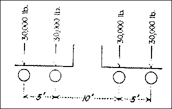
Trolley cars shall be estimated as continuous at 1500 lb. (1.5k) per lineal foot of each track, or as a local concentration of one ash car with axle loads spaced as follows: (Note: the ash cars are special cars used by the B. R. T. for removing ashes, etc.)

The roadbed for trolley cars on bridges shall be assumed as 12 ft. wide, and shall be capable of carrying the loads specified for roadway of bridges.
The roadway load for bridges shall consist of a uniform load of 120 lb. per sq. ft. of surface, or a local concentration of 40k on one axle with a wheel gage of 8 ft. This load may be assumed to cover a space of 12 ft. wide by 40 ft. long.
The roadway load over subways shall consist of a uniform load of 600 lb. per sq. ft. of surface, or a single local concentration of 200k on four wheels, 12 ft. between axles and 1 ft. gage. These concentrated loads shall be assumed to be distributed over an area of 2x2 ft. on the pavement and thence through the earth at a slope of one-half to one. Sidewalks over subways shall be assumed as loaded at 600 lb. per sq. ft.
Footwalks for bridges and platforms of elevated R.R. stations shall be estimated as loaded at 100 lb. per sq. ft. of surface. Subway platforms shall be estimated as loaded at 150 lb. per sq. ft. of surface.
Impact. Loads due to trains or trolley cars shall be increased for impact in accordance with the following formula:

No increase shall be made for impact to horizontal loading (centrifugal or traction forces.)
Wind-provision shall be made for wind pressure acting in either direction, horizontally, of 10 lb. per sq. ft.
Traction-provision shall be made for the sudden starting or stopping of a train 100 ft. in length, estimating the coefficient of sliding friction at 10%.
Temperature-provision shall be made on bridges, for a variation in temperature at 120 degrees F.; a difference of 40 degrees in the temperature of the chords of the same truss, or in that of adjacent trusses of the same structure shall be considered in spans of more than 300 ft.
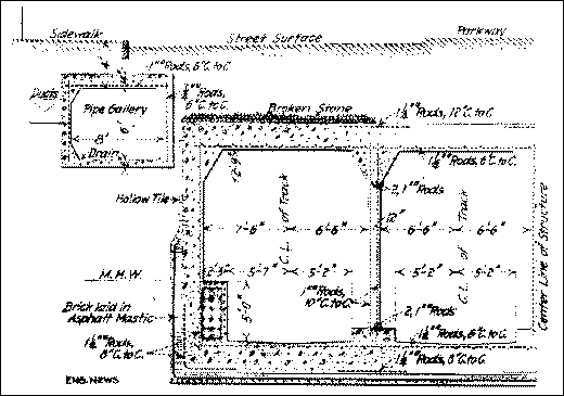
Fig. 10. Half section of B.R.T. subway on Fourth Avenue, Brooklyn, built in reinforced-concrete with pipe gallery under sidewalk. (Click image to enlarge.)
The following table shows the unit stresses (1k = 1000 lb.) allowed for steel used in the structure taken in conjunction with the foregoing loadings.
| Nature of Stress | Medium Structural Steel | Cast |
|---|---|---|
| Tension (net) | 20k * | 16k |
| Compression (1 Diam.) (Gross) | 20k | 20k |
| Compression (12 Diam.) (Gross) | 16.5k | ... |
| Compression, Columns |  | ... |
| Bending (Beams, outer fiber) | 20k | ... |
| Bending (Pins, Rivets and Bolts) | 30k | ... |
| Shear (Pins, Rivets, web) (Net sec.) | 15k | 16k |
| Bearing (Pins, Rivets and Bolts) | 30k | ... |
| Bearing (Roller) per lineal in. | 0.75kd | ... |
| Notes: l = length of column. in inches. r = least radius of gyration of cross-section, in inches. d = Diameter of roller, in inches. * Compression members in steel and iron shall not receive greater unit stress than that allowed for 12 diameters. | ||
When beams and girders are embedded in concrete, the concrete will be assumed to take 20% of the loading. In case of field rivets, 25% excess will be added to the number of rivets required as above. (When machine-driven this may be reduced to 20% excess.)
Preliminary Investigation. Extensive borings, both wash and core, were taken before construction to determine as nearly as possible the character of the subsoil, depth to rock, etc., although the latter is extremely irregular. All existing structures, both above and below ground, were located as well as possible so that proper provision might be made for taking care of them, though the actual final disposition of many of the small pipes, etc., was not determined, until they were all uncovered by the excavation and accurately located.
General Design. Speaking generally, the present designs are based on the use of structural-steel frames with concrete jack arches between. The use of reinforced concrete is very limited. It seems to be generally considered that the use of the structural-steel frame greatly facilitates the support of the street decking during construction, because just as soon as a bent is set up and riveted, the load may be transferred to it.
Fig. 11. B.R.T. subway on Broadway at Canal St. showing very heavy floor to resist upward pressure of water. (Click image to enlarge.)
Under the requirement that the street surfaces shall be maintained and their use for vehicular and other traffic be uninterrupted, it is generally necessary, on account of the width of the excavation, to carry this decking on timber supports, which, as will be seen later, fill up a large part of the excavated space. The construction of reinforced-concrete structures under these conditions is, therefore, somewhat difficult and liable to be patchy, but by proper care in arranging the timbering, the steel-framed bents can be erected easily.
The usual members employed in the steel-frame type of construction in these subways are small enough to be easily handled, so that reinforced concrete has little advantage in the use of small construction units. The ease of construction of the steel-frame structure, and advantages of support more than outweigh any disadvantage in the necessity of using skilled steel erectors, as against the supposed ability to use unskilled labor for reinforced concrete, even though the form work for the concrete with the steel structure is little less than it would be for ordinary reinforced concrete. Fig. 10 shows the reinforced-concrete design adopted in 1908 for the 4th Ave., Brooklyn, lines, which, however, were built mostly in open cut.
Fig. 12. Reinforced-concrete subway on Lexington Avenue. (Click image to enlarge.)
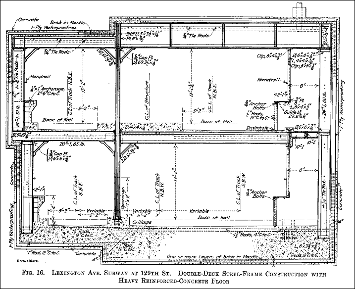
The use of the specially rolled "bulb" angles, used on the original subway, has been abandoned and only standard steel shapes are used. Usually the columns rest directly on the concrete, as shown the normal sections, Fig. 8, but in certain places I-beam grillages are provided. No stone-block footings are used. Where the ground is soft or where water pressure exists, specially designed floors are necessary. One of the most important of these places is at Canal St., where the subgrade of the lower level is 40 ft. below mean high water or normal ground-water level. The heavy girders and thick concrete floor required at this point is shown in Fig. 11. A typical floor to meet conditions below ground-water level is shown in Fig. 15, which is a cross-section of part of the Lexington Ave. subway, where the line passes over what seems to have been an old swamp. This special type was designed principally for the purpose of carrying the structure on the soft ground. Just north of this, at Lexington Ave. and 128th St., where the subgrade is considerably below the water level, a typical design (Fig. 16) of reinforced concrete, for resistance to water pressure in rock is used.
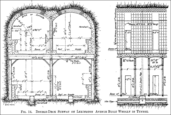
On account of the fact that the New York rock, a micaceous gneiss, is well known to present difficulties of support, that is, on account of bad seams, etc., to be "heavy" in places, it was decided to use a reinforced-concrete lining for the deep-level tunnels under Lexington Ave. It was found on opening up the work, however, that the necessary temporary supports of timber made this type of construction difficult to execute satisfactorily, and a change was, therefore, made to the design shown in Fig. 13. This, as will be seen, permits the construction of the center wall and the haunches with the steel columns and longitudinal I-beams, so that a direct center support can be built to the roof, which is generally sufficient for support of the overlying rock without timbering during the construction of the concrete arches.
Fig. 13. Alternative design for center wall using structural steel instead of reinforced-concrete. (Click image to enlarge.)
The unstable character of the rock and the variation in thickness of the cover involved some changes in the location of the tunnel portals, making it necessary to shift them back in almost every case to get sufficient depth of overlying rock cover. This contingency is of course covered by the provision in the contract for slight variations in total quantities. The heavy ground on some of the sections on Lexington Ave. necessitated the design of considerably heavier steel sections, as shown in Fig. 17, for use at these places.
Further notes in regard to the construction of special sections, such as the Harlem River Tubes, steel and reinforced concrete elevated sections, etc., will be found under their respective headings.
Cross-Sections. During the early days of the Public Service Commission (1907-1908), there was considerable discussion in regard to the desirable dimensions of the cross-section of the new lines proposed at that time as extensions and further developments of the rapid transit lines then in operation. It was not thought advisable to conclude further operating contracts on the basis of those made for the original subway, and it was found difficult to arrive at any other which was agreeable to both parties. It was then decided to go ahead with the construction of the 4th Avenue Brooklyn line and Centre St. loop, leaving the question of operation to be decided later. It was thought that if neither the Interborough nor B. R. T. would meet the views of the Commission in regard to terms of operation, a third party might be found, and as there then seemed to be a possibility that this might be one of the existing steam railroad lines, it was decided to provide clearance for standard railroad equipment and the designs of these two sections were modified accordingly to provide this. As all doubt in regard to the future operation has now, however, been eliminated, it has not been thought necessary in the design of the new lines now to be built to provide for larger equipment than it is known will be used, and the clearances decided on for the new lines are only slightly larger than those provided in the present subway, as is shown in the following table, and in more detail in the typical cross-sections which are shown.
Fig. 14. Double-deck subway on Lexington Avenue built wholly in tunnel. (Click image to enlarge.)
In Fig. 8 (of the previous article) is shown a cross-section of the 7th Ave. line of the Interborough, which is the minimum section for the new lines. Figs. 12. and 14 show the Lexington Ave. line, which is to be operated by the Interborough, but which was designed before the question of operation was definitely decided. Fig. 11 shows the cross-section of the Broadway-59th Street route of the B.R.T. The following table shows a general comparison of the dimensions of the original subway and those since adopted.
| Height above top of rail | Width * | |
|---|---|---|
| Original subway | 12 ft. 4 in. | 12 ft. 6 in. |
| Fourth Ave. Brooklyn and Centre St. loop | 14 ft. 6 in. | 14
ft. 0 in. |
| New subways- B.R.T. | 12 ft. 8 in. | 14 ft. 3 in. & 13 ft. 6
in. |
| New subway-Interborough | 12 ft. 3 in. | 13 ft. 6 in. & 13
ft. 0 in. |
| * From center of columns between tracks to face of side wall. (Columns about 8 in.) Note: These are dimensions on tangents and are increased on curves to provide equivalent clearance. | ||
Fig. 15. Floor on section 12 of I-beams and concrete. (Click image to enlarge.)
As is shown on the various cross-sections, provision is made for building the conduits for the electric wires, in a side-bench wall with a walk on the top, instead of placing them in the sidewalls, as in the old subway.
The standard track spacing for four-track subways finally adopted is as follows; from the center line of the four tracks to face of sidewall:

Cross-sectional dimensions of other rapid transit subways in the United States are approximately as follows, there being many minor variations:
| Height above top of rail | Clear width | |
|---|---|---|
| Boston, Tremont St., 1898 | 13 ft. 10 in. | 12 ft. |
| Boston, Washington St., 1901 | 14 ft. 5 in. | 12 ft. 2 in. |
| Cambridge, 1910. | 14 ft. 9 in. | 12 ft. 6 in. (a) |
| Philadelphia, 1907. | 14 ft. | 12 ft. |
| H. & M. 6th Ave., 1908. | 12 ft. 10 in. | 13 ft. (b) |
| Note (a)-The Cambridge subway is large enough to take standard steam railway equipment, the tracks are 12 ft. on centers. Note (b)-Sidewalk over duct bench at side. | ||
Fig. 16. Lexington Avenue subway at 129th Street. Double-deck steel frame construction with heavy reinforced-concrete floor. (Click image to enlarge.)
The question of cross-section is of considerable importance. It is determined largely by the size of the cars, the economic limit of which is controlled largely by the time necessary to load and unload them at express stations during the rush hours. Under present operating conditions, the splicing of trains is determined probably as much by the length of station stops as by ability to run the trains more closely together between stations. It is probably difficult to determine the exact economic dimensions of a car which will hold the maximum number of people and at the same time permit the minimum time of stopping. As has already been pointed out, the B. R. T. has decided to use a larger car, but the Interborough will probably of necessity be obliged to continue the use of equipment interchangable with that now in use, and therefore all new lines which are to be used exclusively by this latter company are designed on that basis, only very slightly larger than that now in use.
Fig. 17. Heavy steel sections in center wall, Lexington Avenue line at 59th Street. (Click image to enlarge.)
The cross-section has also, of course, an important bearing on the question of ventilation; this, however, is discussed more fully under that heading.
On some of the routes when the designs were made and construction started, it was uncertain whether they were to be operated by the B. R. T. or the Interborough; provision was therefore made as is shown in the sketch, Fig. 18, for an adjustable edge to the platforms, so that either the 9 ft. Interborough or the 10 ft. B. R. T. cars could be used.

Track Construction. A standard track construction has been adopted for all the new lines, by conference and agreement between the two operating companies and the Public Service Commission. Rails are to be 100 lb. openhearth B section of the Am. Ry. Eng. Assoc. Ties are to be yellow pine 6x6x8 untreated, with flat-bottom shoulder tieplates 7.5x9x0.5 in. and 6 in. cut spikes. In the subways, traprock ballast 0.5 to 1 in. will be used as a cushion over the concrete floor; as the headroom is limited there will be only about 6 in. of drainage provided by the drains in the concrete floor. Judging by experience with the ties in use on the present rapid transit lines it has been thought that treatment by creosote or other preservative will not be necessary.
Fig. 18. Typical cross-section of track. (Click image to enlarge.)
Guard rails are to be used on all curves of less than 2000 ft. radius; those under 700 ft. radius will also have rail braces on the guard rails, as well as for the outside rails. Rolled manganese rails are to be used practically entirely for all frogs, switches, cross-overs, etc., and on all curves less than 700 ft. radius. In regard to the necessity for the use of manganese rails, which cost about 2.5 times as much as openhearth, reference may be made to the experience of the Boston Rapid Transit lines, (Eng. News, Oct. 22, 1908, p. 458), where on a certain curve bessemer rails lasted only 60 days, a cast manganese rail had shown only about 0.5 in. wear in six years. There is of course, not only the wear of the rail to be considered, but the cost of changing due to the abnormally high cost of track work under the extremely heavy traffic and in the confined space in the subways.
At stations, in order to facilitate cleanliness and sanitation, a special type of track construction similar to that used in the Pennsylvania terminal station in New York (see Trans., Am. Soc. C. E., Vol. LXIX, p. 305) and the Detroit River tunnels (see Trans., Am. Soc. C. E., Vol. LXXIV, p. 349) is to be used. A cross-section is shown in Fig. 19.
The track material is to be bought by the Public Service Commission under contracts and at unit prices to be bid for the various items required; it is to be stored and issued on requisition to the operating companies who will install the track as part of the "equipment".
Track Layouts. The arrangement of tracks at junction points, so as to avoid crossings at grade, with the consequent delay, as well as danger, has been the subject of considerable thought and study. In the present subway there are three junction points, at Bowling Green, City Hall, and at 96th Street. The first two being merely junctions of double track lines, where only one class of trains, either local or express, has to be cared for on each route, did not present any particular difficulty, it being only necessary to depress one track under the other two. At 96th St., however, where two double-track lines come together in a four-track section, and where express and local trains have to be directed from any one line to any of the others (in the same direction), the problem is more complicated.
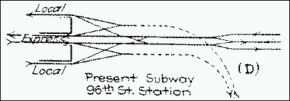
The present layout at 96th Street is shown diagrammatically at Fig. 20 (D); it will also be noted that the switches and slip crossings are all on the north side of the station, and that as trains from either branch may and do continue as either local or express, there is frequently some delay to trains before they can approach the crossings to enter the station on the proper track. This would not be noticeable on lines of ordinary traffic, but under the conditions existing during the morning and evening rush hours in New York, the slightest delay may be magnified into a congestion of the whole system.
The number of such junction points on the new lines has been considerably increased and typical methods of overcoming the difficulties are shown in the three diagrams, Fig. 20, (A), (B), and (C).
Fig. 20 (A) (Click image to enlarge.)
So far as possible in all the designs for the new lines the engineers have tried to avoid any slow points, such as switches, crossings. etc., in places other than close to stations where trains must stop, and to locate them on the farther side rather than on the near side where they would be reached before the train enters the station, and where in case the line is not clear the train would have to make a signal stop before reaching the switch as well as the station stop after.
Fig. 20 (B) (Click image to enlarge.)
The diagram at Fig. 20, (A) shows the track layout at 125th Street on the Lexington Ave. line. It will be noted that coming from the north, trains from either branch reach the station without crossing any switches, are both on the same level and on their same respective sides of the station. Continuing south, those trains which become expresses from this point, pass the required switches within 300 or 400 ft., while the locals have a switch, which is, of course, a slow point, at 119th St. (about 1,500 ft. beyond the station). This, however, is of little importance, so far as causing any delay in the south bound movement of the local trains is concerned, as their next station stop is at 116th St.
Fig. 20 (C) (Click image to enlarge.)
Coming from the south the expresses reach the upper level in the east side over practically a straight line with no switches, with just enough ascending grade to slow them down. Leaving, they take one or two switches as they are diverted to either the east or west branch, but both within 300 ft. of the station. The locals coming from the south have one or more switches to pass before they reach the station; this, however, is not of importance especially as they do not anywhere come in contact with the expresses. As may be seen these latter switches are not necessary for the operation of through trains, as trains from either side of the station going north reach either branch without a crossing of tracks of trains going in the opposite direction, but are put in for convenience to provide two extra side tracks for any emergencies of operation at this junction.
Fig. 20 (D) (Click image to enlarge.)
The other two diagrams are self-explanatory, except to say that at Eastern Parkway and Utica Ave., Fig. 20 (B), the arrangement is not quite so elaborate as there is not expected to be such heavy travel on this section as to warrant large expenditures to prevent short delays.
