Chapter 13. Design of Steel Elevated Railways
From nycsubway.org
The New York Rapid Transit Railway Extensions · Engineering News, 1914
By Maurice R. Griest Assistant Designing Engineer, Public Service Commission for the First District; Engineering News, May 20, 1915.
The new rapid-transit lines now under construction in New York City include 144 miles of subway and 106 miles of elevated track to be built by the city, and also third-tracking and extensions of their present elevated lines by the operating companies totaling 67 miles of track. Plans for the city-built lines are made by the Public Service Commission, while plans for the extensions of the present elevated lines are being made by the companies subject to the approval of the commission. In this chapter some features of the design of the city-built elevated lines will be considered.
Open-Floor or Solid-Floor Construction.
A subway is preferable to an elevated line from the standpoint of the property owners along the route, and a general policy of not constructing elevated lines in the central congested districts has been followed. On the other hand, the cost of a subway is so great that, with the city's present financial condition, a universal subway system is out of the question. The program therefore provides trunk-line subways through the central districts of Manhattan and Brooklyn, with elevated feeders in the outlying districts.
When the Triborough system was under consideration in 1910 it was proposed to build elevated extensions or feeders with ballasted track on a solid concrete floor to reduce the noise to a minimum, thereby reducing somewhat the objections to the elevated lines. When the present dual-system contracts were prepared the city's financial condition made it imperative that the feeders be built as cheaply as possible. The relative cost of subway and elevated lines with ballasted floor and with open floor for the 106 miles of proposed elevated tracks are as follows:
Cost of Subway and Elevated Structure
| Type | Per Lin.Ft. of Structure | Total |
|---|---|---|
| Three-track subway | $300 to $500 | $63,000,000 to 105,000,000 |
| Three-track elevated, solid floor | $200 | 42,000,000 |
| Three-track elevated, open floor | 125 | 26,000,000 |
The open-floor construction would cost about $16,000,000 less than the solid-floor and from $37,000,000 to $69,000,000 less than the subway. It is therefore evident why open-floor elevated construction was used for the feeders in outlying districts.
Type of Bent.
The elevated lines consist largely of a three-track construction, providing two tracks for local service and a center track for rush-hour express service in the direction of the maximum traffic (returning the express trains empty over the local track). In general a two-column bent was found to be most satisfactory and most economical; it has been adopted uniformly except in special cases, such as at stations, where the structure is widened to such an extent that three or four columns are necessary.
Columns in Roadway.
With the two-column bent there are in general two practicable positions for the columns-namely, in the roadway and on the sidewalk near the curb. As any obstruction in the roadway is always a source of danger to traffic, it is desirable to keep the roadway clear of columns as far as possible. On the other hand, in wide streets a material saving in cost is effected by placing the columns in the roadway. Furthermore, the appearance is largely improved by eliminating wherever possible the long transverse girders projecting beyond the longitudinal stringers. The cost, appearance and obstruction to street traffic were therefore factors in determining the column location. The widths of roadway for various street widths have been fixed by resolution of the Board of Estimate and Apportionment as follows:
| Street width, feet | 100 80 70 60 |
| Roadway width, feet | 60 44 36 30 |
With a 60-ft. roadway it was not considered practicable to place the columns on the sidewalk, as the cross-girders would be over 63 ft. long and would project 16.5 ft. on each side beyond the outside longitudinal stringer. With columns in the roadway the exact location was determined by their relation to the longitudinal stringer (affecting the strength, rigidity, appearance and cost of the structure), to surface-car tracks, and to the lines of vehicular traffic.

Fig. 90. Two Possible Locations of Elevated Railway Columns in Street. (Columns at curb and column under outer stringer.)
Structurally it is desirable to place the columns under the outside stringer. With this construction, longitudinal curved brackets can be placed advantageously on the column under the stringer, thus reducing the unsupported length of column, increasing the rigidity of the structure and producing a pleasing appearance. By placing the columns between the stringers of the outside tracks the section of the cross-girder is reduced slightly and the section of the column increased correspondingly, as longitudinal brackets are not feasible with this construction. The brackets increase the cost by $1 to $1.50 per foot of structure; but this cost, other things being equal, would be warranted by the additional rigidity of the structure and the improved appearance.
Cars to be operated by the Interborough Rapid Transit Co. are 9 ft. wide, 52 ft. long and 36 ft. c. to c. of trucks; those to be used by the New York Municipal Railway Corporation are 10 ft. wide, 66 ft. long and 47 ft. c. to c. of trucks; all are standard-gage. Stringers are spaced 5 ft. c. to c., so that practically all stress in the ties except direct compression is eliminated. For safety it is desirable to have about 3 ft. clear between cars on adjacent tracks. For Interborough operation, however, the tracks were spaced 12.5 ft. c. to c. on tangents, to provide additional clearance to the through girders over the station mezzanines, while for the Municipal corporation's operation they were kept 13 ft. c. to c. With the columns placed under the stringers the transverse column spacing is therefore 30 ft. and 31 ft. c. to c. respectively for the two companies, dividing the roadway as shown in Fig. 90.

Fig. 91. Location of Columns Adopted For Wide Streets. (On streets 44 ft. wide or less, the columns are placed inside the curb, with 47 ft. 4 in. maximum spacing.)
Trolley tracks are usually spaced about 10 ft. c. to c., except where a greater width is required on account of center poles, in which cases 12.5 ft. and 13 ft. are the most common spacings. When an elevated structure is built over such a line the poles are removed and the trolley wires supported from the structure. The tracks can then be spaced 10 ft. For safety to passengers a clearance of about 3 ft. from the side of the car to the face of the column is desirable-that is, about 7.5 ft. from the center line of track to face of column (although some lines are now operated in Manhattan with only 1 ft. 10 in. clear). With tracks spaced 10 ft., and 7 ft. 4 in. clear from center of track to face of a 16-in. column, the minimum spacing of columns transversely is 26 ft.
It is essential that the columns be placed far enough from the curb to allow two lines of vehicles to pass between. A minimum of from 15 to 16 ft. is required for safety. To place the columns, therefore, for greatest safety and efficiency of roadway requires a spacing of about 26 ft., as shown in Fig. 2. With columns spaced 26 ft. two lines of vehicles can pass between the curb and column and one line on each car track, six in all. With 30- or 31-ft. spacing, only one line can safely pass between the curb and column, or four in all, thus giving a 66.6% roadway efficiency as compared to the 26-ft. spacing. The conservation of the street was deemed of greater importance than the slight structural advantage of the wider spacing. Therefore 26 ft. was adopted as the transverse spacing. except in a few isolated cases affected by special local conditions.
Columns on Sidewalk.
With roadway width 44 ft. or less, it is evident that columns cannot advantageously or safely be placed in the roadway. In order that the columns may occupy as little of the sidewalk space as possible, and at the same time be protected from traffic by the curb, they have been placed uniformly with the center 1 ft. 8 in. from the curb. With 44-ft. roadway the transverse spacing is therefore 47 ft. 4 in.
Longitudinal Spacing of Columns.
Except as affected by local conditions, the longitudinal spacing of columns was determined by economy. Fig. 92 shows diagrammatically the cost of those items of typical elevated construction between stations which vary with the span length, plotted for various spans both for 26 ft. and for 47 ft. 4 in. transverse spacing of columns.* [ * These costs are based on present average prices, which are unusually low, particularly for steel, whose cost makes up about 80% of the cost of an elevated structure exclusive of track, signals and station finish.] An inspection of this diagram shows that 50 ft. is the economical spacing and that there is little choice of other span lengths from 40 ft. to 60 ft., above which point the cost increases rapidly with the span length. The 50-ft. longitudinal spacing of bents was therefore adopted as the standard.

Fig. 92. Effect of Span Length on Cost of Three-track Elevated Railway. (Excludes track, stations and ducts. Average prices of recent contracts used as follows: Steel, $54 per ton; cast iron, $48 per ton; concrete, $7 per cu.yd.; excavation, $2 per cu.yd.; paving, $3 per sq.yd.)
At the cross-streets columns are spaced so that the interference with traffic is the minimum, 60 ft. and longer spans often being required at these points. Uniform spacing of bents between streets is often impossible on account of local conditions, varying block lengths and interference with surface and subsurface structures. The 50-ft. spacing, however, has been used as far as practicable.
Type of Construction.
A deck plate-girder type of construction has been used exclusively, except over station mezzanines and in isolated cases where special conditions require other construction.
A half-through girder construction with longitudinal girders between the tracks has been used over the station mezzanines to reduce the depth of construction so that the climb from street to platforms will be a minimum. It is uneconomical, however, and if continuous would be a source of danger to workmen, as it gives them less chance to escape from approaching trains, particularly on the center track.
A through-truss construction is evidently impracticable with columns placed in the roadway. With columns in the sidewalk it is uneconomical and undesirable, as it obstructs light from abutting property to a greater extent.
Latticed stringers are from 10 to 15% lighter than plate-girder stringers of the same span. The cost of fabrication of the latter, however, particularly without coverplates, is about 10% less than of a latticed girder without connection plates and 15% less than of a latticed girder with connection plates. The first cost, therefore, is practically the same in either case. Depreciation and maintenance costs of plate-girder construction are less than for latticed girders; details are simpler and the structure is more rigid. Plate-girder stringers were therefore adopted.
Expansion Joints.
On the elevated extensions of the present subway, expansion joints were placed about 200 ft. apart, or about every fourth bent. In order to reduce to a minimum the tension of the top rivets of the stringer connection due to the combination of the deflection of the stringer and contraction, the distance between joints has been reduced to about 100 ft., or an expansion joint is provided at alternate bents. The cost is thus slightly increased, as the expansion detail of the stringer is slightly heavier than the detail at the fixed end, and additional bracing is required. It is expected, however, that this increase in first cost will be more than offset by a reduction in maintenance charges for replacing rivets in the stringer connections.
The expansion joint which has been used exclusively on city-built lines is shown in detail in Fig. 93. It consists essentially of a 4-in. half-round pin bearing on pin-plates on the stringer and sliding on a seat made up of angles and plates attached to the cross-girder. The thickness of plates on both seat and stringer has been made uniformly 3 in. for all spans. The pin is held in place and the stringer held in line by small guide-angles attached to the end stiffeners on the stringer. The particular advantages of this joint are its simplicity of construction and ease of erection, its accessibility for painting and inspection and the certainty of a uniform bearing on the seat. The connection of the seat to the cross-girder has been designed for the maximum shear combined with the tension on the rivets due to the maximum moment with the pin bearing on the extreme edge of the seat.

Fig. 93. Details of Elevated-Railway Construction. (New City-built lines of dual rapid-transit system, New York City.)
Provision has been made for a contraction or expansion of 1-2 in. from normal temperature, which is undoubtedly slightly in excess of the maximum to be expected, but allows for slight inaccuracies in placing columns and in the milled length of stringers. It is desirable to reduce the opening as far as possible, in order that the pin will not approach dangerously near the edge of the seat at extreme low temperatures.
This joint has been used satisfactorily on previous elevated extensions of the subway (contract 1). The elevated structures have been designed for the following loads:
1. Dead-load. The weight of track, including ties, rails, guard-rails, service walk, signals, etc., estimated at about 400 lb. per lin.ft. track, in addition to the weight of the structure itself.
2. Live-loads. A series of concentrations approximating the weight of the heaviest equipment it is proposed to operate on the dual system: 22,750 lb.-5 ft. 6 in.-22,750 lb.-29 ft. 11 in.-30,240 lb.6 ft. 8 in.-30,240 lb.-8 ft. 8 in.-30,240 lb.-6 ft. 8 in.-30,240 lb.-29 ft. 11 in.-22,750 lb.-5 ft. 6 in.-22,750 lb.-9 ft. 3 in.30,240 lb.-6 ft. 8 in.-30,240 lb.
3. Horizontal forces. (a) Wind pressure of 30 lb. per sq.ft. on the exposed surface from the top of train to the bottom of structure; (b) the sudden starting or stopping of a 500-ft. train, estimating the coefficient of sliding friction at 10%; (c) centrifugal force equal to 0.020 time the product of weight of moving cars and degree of curve, the coefficient to be reduced by 0.001 per degree for curvature between 3 and 20 degrees.
4. Impact. With the track resting directly on the stringers the effect of the impact from the live-load will be as great as, if not greater than, on bridge spans. Live-load stresses (except for horizontal forces) have therefore been increased for impact in accordance with I=125 - 1/2 (sqrt 2000) L - L2 where I = impact increment in per cent. and L = length in feet of loaded track which produces the maximum stress in the member.* [ * For example, with 50-ft. spans, L for the stringer is 50 and I = 86%; for a cross-girder in which maximum stress is produced with one track loaded L = 100 and I = 70%; and for a cross-girder in which maximum stress is produced with three tracks loaded L = 300 and I = 36%. Impact is added similarly to column stresses.]

Fig. 94. New Elevated Structure with Columns in Street. (White Plains Road, Bronx Borough.)
On a three-track line it has been assumed that the tractive force will at no time exceed the effect of two trains acting in the same direction at the same time. On a two-track line, where the probability of trains on each track acting together is greater in proportion, provision has been made for five-sixths of the full tractive force. These assumptions, which are based on the fact that a considerable (though indeterminable) part of the tractive force is transmitted to adjacent spans through rails and expansion joints, are believed to be conservative. No data are available to determine the amount of distribution, but observation of the present lines shows that it is material. Furthermore, the probability of a train on each track at any span starting or stopping at the same time, so as to exert full tractive force on each track in the same direction, is remote. Designed on these assumptions, the new structures, at a very small additional initial cost, will have greater rigidity against horizontal forces than the existing elevated extensions. This rigidity, it is believed, will increase the life of the structure and reduce the maintenance costs.
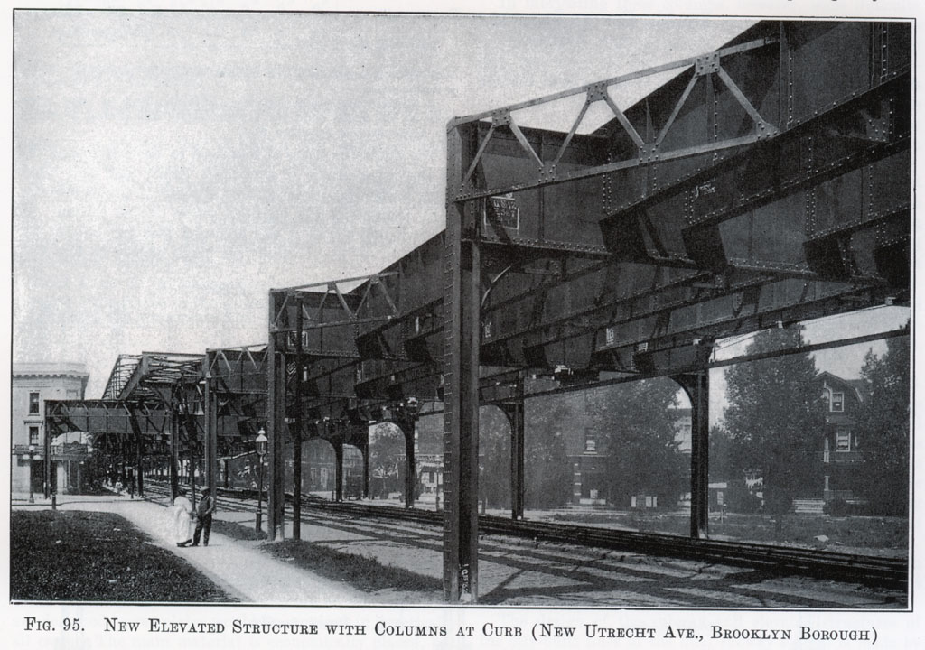
Fig. 95. New Elevated Structure with Columns at Curb. (New Utrecht Ave., Brooklyn Borough.)
Design of Stringers.
For spans varying in length from 45 to 60 ft. the economical depth of stringer is about 5 ft. For uniformity of appearance and details it is of course desirable to keep the depth constant as far as possible. As the number of spans exceeding 60 ft. is small, 5 ft. was adopted as the standard depth, except for spans of 70 ft. or over.
It is desirable to avoid cover-plates on stringers to reduce the cutting of ties over rivet heads. In addition the top cover-platemust be extended full length to maintain a uniform distance from top of steel to base of rail. With 70-ft. span and 5-ft. depth, either cover-plates or flange angles thicker than 7/8 in. (which must be drilled from the solid) are required. Furthermore, in the long spans the 5-ft. depth is uneconomical and the deflections are excessive unless the allowable flange stress is reduced. It seemed necessary, therefore, to sacrifice appearance to economy and good practice by increasing the depth to 72 in. and 78 in. for spans 70 ft. long or over.
In cases where the length exceeded twelve times the depth of stringer, in order that the deflection (in inches) should not exceed 1/50 the span (in feet), the allowable stress was reduced to the value given by the following formula: Stress = U H / span in feet. where U = the usual allowable unit-stress and H the depth of the girder in inches.
To support the compression flanges of stringers and provide the usual truss for horizontal forces, lateral bracing between the stringers of each track was provided as shown in Fig. 93, with cross-frames at intervals varying from 12.5 to 20 ft., depending on the span lengths. In addition lateral bracing was placed between stringers of adjacent tracks in one fixed span in each expansion panel in order that the tractive force from the center track should be transferred to the columns without producing lateral bending on the cross-girder.
Where the columns are outside of the outside stringer the tractive force was carried to the column by a strut from the outside stringer at the first cross-frame. The stress to be transmitted was small, requiring only two angles. For stiffness, however, latticed struts were provided, which will be further discussed under the head of columns. Where the columns are between the stringers of the outside tracks, the tractive force was transmitted by a channel riveted to the bottom flanges of the stringers, to the stiffeners of the cross-girder over the column and thence to the column.
The top of the stringer is 9.25 in. above the top of the cross-girder, so that the top flange angles extend over to the center of the cross-girder and are supported on it by seat-angles. This detail is arranged to provide continuous support for the ties, to make unnecessary special wide spacing at the flanges of cross-girders. The rivets in these seat-angles are intended to support the ends of flange angles only and are not intended to produce continuity in the stringers-which were in all cases designed as simple spans. Splicing the stringers for continuity was considered, but was abandoned because the detail was too heavy for ultimate economy, and continuity over expansion joints was impossible. The end-connection angles were set against the webs without fillers and not carried over the lower flange angles to a bearing on the outstanding leg, as this was considered unnecessary. A saving of nearly $1 per lin.ft. of structure was thereby effected.
Cross-Girders.
As previously described, all transverse bending stresses have been eliminated so far as practicable, so that the design of the cross-girder followed the usual practice of girder design. For column spacing of 47 ft. 4 in., a 6-ft. girder was used generally, while a 6-ft. girder was more economical for the 26-ft. column spacing. Stiffeners are of course provided over the column to transfer the reaction to the column. Intermediate stiffeners were provided to stiffen the girder in shipping and handling only, as the stringers when connected stiffen the web sufficiently to prevent buckling.
Design of Columns.
The columns have been designed for a combination of direct load and bending stresses due to wind, centrifugal and tractive forces. In combining the direct and bending stresses the following limits were adopted as giving a safe design:
1. With the direct load alone, the stress per square inch should not exceed that allowed by the Public Service Commission formula Stress = 20,000 / (1 + l2/8000 x2>) with a maximum of 14,000 lb. per sq. in.
2. With direct load combined with bending in one direction only the stress should not exceed 20,000 lb. per sq. in. on the extreme fiber.
3. With direct load combined with bending in both directions at the same time the stress should not exceed 25,000 lb. per sq. in. on the extreme fiber.
The allowable stress is increased in the latter cases due to the infrequency of maximum direct load and maximum horizontal forces in both directions simultaneously.
In computing the bending stress in the column due to horizontal forces it was assumed that the column was fixed both top and bottom (see detail of base in Fig. 93).
Four 1 1/4-in. anchor bolts attached to the base of the column by seat-angles, with stiffeners so arranged that the nut has a direct bearing over the stiffeners, have been designed to anchor the columns. With the columns spaced 26 ft., longitudinal bending stresses are transmitted into the column by 5 x 1/2-in. splice-bars attached to the stiffeners on the cross-girder and to the column channels. The stiffeners on the cross-girder over the columns are fixed at the bottom of the stringers by the channels previously described, while fixity at the top is secured to a large extent by the transverse stiffness of the top flange of the girder, which is held rigidly by the adjacent stringers, less than 2 ft. from the column. This bending in the flange occurs at a point where the vertical bending stresses are small and does not therefore overstress the flange. While no tests of this detail have been made, it is believed that at least a fair degree of fixity in the column longitudinally is obtained.
When the columns are placed beyond the outside stringers, in place of the splice-bars just described, the outside channel of the column is extended to the top of the crossgirder and riveted to the end stiffeners, transmitting the longitudinal bending from the girder to the column. A latticed strut 50 in. deep extends from the stringer at the first cross-frame to the column (see Fig. 93; the strut is also shown clearly in the view, Fig. 95). With this depth it is believed that the column is fixed at the top.
The columns and the cross-girder being connected to form a rigid portal, the wind force produces a bending stress in the cross-girder. This, however, is small, amounting with columns spaced 47 ft. 4 in. to less than 1%, and with columns spaced 26 ft. to only 5% of the maximum stresses due to direct load. The effect of wind on the cross-girder has therefore been neglected.
In selecting the type of column no section was considered which did not permit inspection and painting, thus eliminating all box types (see Fig. 96).

Fig. 96. Column Sections of Elevated Railways. Fig. 97. I-Beam Distortion.
Section A, with two channels laced, was used extensively on the present Manhattan Ry. Co. elevated lines. With the loads for which the columns on the new lines are designed, cover-plates would be required in practically all cases. The main material is economically placed, but this advantage is more than offset by the loss (so far as effective section is concerned) in the lacing bars, amounting to about 12% of the total weight of the column, or 15 to 18% of the weight of main material. As a result the column is not so economical as Section C, and is less satisfactory as to details.
The elevated extensions of the present subway, Contract 1, have bulb-angle columns, Section B, usually without cover-plates. On account of the difficulty of obtaining bulb angles except in large quantities, and also because the section is less efficient and economical than a channel-and-I-beam column, a bulb-angle type has not been used on the dual system.
Section C is similar to Section A, except that the channels are connected by an I-beam instead of by lacing. The beam is ineffective in resisting bending about axis X-X. The material is effectively placed, however, for resisting bending about axis Y-Y and for carrying direct load. For the elevated loading this section is particularly efficient and economical. The material in the column with a built-up instead of a rolled I-beam, Section D, is slightly less economical, and in addition there are two extra lines of rivets. The I-beam-and-channel type, Section C, was therefore adopted.
In fabricating these columns, however, some difficulty has developed. The beams as they come from the rolls are invariably slightly warped, as shown exaggerated in Fig. 97. When the channels are attached it has been difficult to avoid a wind in the column. This trouble developed after the details for a number of sections were completed. To avoid this difficulty it has been suggested that on future work the I-beam-and-channel column, Section C, be abandoned for the built-up Section D.
Fig. 98 shows the typical arrangement of tower construction which has been found to be economical where the height from street to base of rail exceeds 30 ft. A spacing of 35 ft. between bents of tower span, with standard 5-ft. stringers, proved to be more economical than a shorter span with shallower stringers, and in addition permitted greater duplication of stringers and details and maintained a uniform appearance. The long spans are varied to suit local conditions, a length of about 60 ft. being the most economical.

Fig. 98. Tower Construction, Used For Heights Over 30 Ft.
In order to duplicate pieces, details have been standardized wherever possible. Stiffeners and flange rivets on the stringers and the arrangement of lateral bracing and cross-frames are shown typically in Fig. 99. Cross-frames were spaced at intervals not exceeding 20 ft. Stiffeners were in general spaced about 5 ft. apart, but were placed between the panel-points of horizontal bracing except at cross-frames, thus avoiding notching lateral plates at intermediate points.

Fig. 99. Lateral Bracing and Stringer Riveting.
The average weight of steel, including stations, on two contracts with columns spaced 47 ft. 4 in. is about 11/8 tons (2250 lb.) per lin.ft. structure.
The design of the subway and elevated structures of the city-built lines of the dual subway system is made by the Public Service Commission's engineering staff, of which Alfred Craven is Chief Engineer; Robert Ridgway, Engineer of Subway Construction; D. L. Turner, Deputy Engineer of Subway Construction; Sverre Dahm, Principal Assistant Engineer, in charge of design, and A. I. Raisman, Senior Designing Engineer. The design of the major portion of the elevated lines was made under the immediate supervision of the writer.